| [ Főoldal ] [ Térburkolatok ] [ Üllői vízmű ] [ Modellezés ] [ Úszómedencék ] [ Minolta AF5000 ] [ Eladó AF 5000 ] |
| [ FMS faq ] [ RC-PC interface |
Glow Plug DriverÁbel István
|

|
| [ frissítés magyarul ] [ refresh in english ] |
It has some advantages against the usual designs with NE555, and it may have some disadvantages too.
You are free to build this circuit described below for yourself. Commercial
usage is prohibited without my written permission. The circuit is as is. No
guaranty of working and not blowing your glow plug.
Specification:
Input power:
Output:
| Download SG 3524 data sheet from | |
|---|---|
| Signetics | Texas Instruments |
Advantages:

Description:
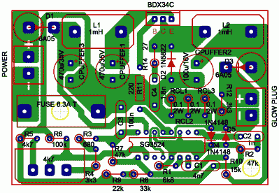
The 5V reference voltage supplied by SG3524 is filtered with C3.
An adjustable reference voltage for the error amplifier is prepared from this 5V by the R3,R4,R5 resistor network, and by the HeatingPot.
R6 ensures keeping at GND the error amplifier input, in case of loose potentiometer.
The voltage sense network is realised with R7,R8,R9,R10. These two networks are designed to keep the input voltages in the common mode input voltage range of the error amplifier.
Output current is measured trough the RCL(1..3) resistors, and fed into the current limiting inputs of SG3524.
D4 and D5 is there for protectional purposes.
Current limiting is active when 200mV is reached at the current limiting amplifier inputs. Output current can be measured externally by sensing the voltage across these
resistors ( in total 0.033 Ohm ).
R1, C1 sets the 40 kHz switching frequency.
R2, C2 are the factory defaults for the compensation input.
BDX34C is fed through R11, by the paralleled outputs of SG3524.
Heatsink ( 7 K/Watt) must be installed on BDX34C.
D1 is for input, D3 for output polarity protection.
The D2,L2,Cpuffer2 network is the main conversion loop.
Input filter is built from L1,Cpuffer1,Cpuffer3.
The purpose of R12 is to give a minimal load for the converter.
The circuit is easy to build, and works reliable. It has to be built into a steel case, because of EMC ( Electro Magnetic Compatibility ).
| Parts List: | |||
|---|---|---|---|
| Description | Quantity | Name | Type/Value |
| Connector | 2 | GLOWCONN POWERCONN | RM = 5 mm |
| Coil ( ferrit core ) | 2 | L1,L2 | 1mH ( described below ) |
| Ceramic capacitors | 1 | C2 | 1n |
| 1 | C4 | 1.8n | |
| 1 | C1 | 4.7n | |
| 1 | C3 | 100n | |
| Electrolit capacitors | 3 | CPUFFER 1..3 | 470µF/35V |
| Resistors, 2/3 W | 2 | R4,R12 | 3k3 |
| 1 | R1 | 6k8 | |
| 1 | R10 | 15k | |
| 1 | R9 | 22k | |
| 1 | R14 | 27 | |
| 1 | R8 | 33k | |
| 2 | R2,R7 | 47k | |
| 1 | R6 | 100k | |
| 1 | R11 | 220 | |
| 1 | R3 | 680 | |
| 1 | R5 | 4k7 | |
| Current sense resistors | 3 | RCL1,RCL2,RCL3 | 0.1 Ohm / 2 Watt |
| Potentiometer | 1 | HEATINGPOT | 4k7 |
| Fuse holder | 1 | FUSE HOLDER | |
| Fuse | 1 | FUSE | 6.3A/T |
| Rectifiers | 2 | D4,D5 | 1N4148 |
| 1 | D2 | 1N5822 | |
| 2 | D1,D3 | 6A05 | |
| Transistor | 1 | Q1 | BDX34C |
| PWM controller IC | 1 | IC1 | SG3524 |
| Heat sink | 1 | HEATSINK | 7.0 K/W |
| Heat sink isolator | 1 | ISOLATOR | TO-220 |
L2 is a 1..3 mH inductor custom made on ferrit core with high current handling capability. I choose a toroid ferrit core with diameter of 17 mm, and a relative permeability of approximately 1600. 34 wounds on this core from a 1.1 mm diameter enameled copper wire made it full and just fitted the needs.
Cpuffer2 has to be low ESR type if long heating periods are required. Because of the excessive amount of current flowing through it, during a longer motor heating session, heating of the capacitor occurs.
Tips for modification:
As You may noticed the circuit is basically a switching voltage regulator with all the technology's bells and whistles. This means with some modification the circuit is useable for other purposes, no only to glow plug heating.
The circuit currently not available from me, but You can build it yourself easily. I currently manufacture interfaces to connect your radio transmitter and your PC to use R/C flight simulators, there are 2 versions available: a COM port PIC interface for FMS, and a GAME port interface realised with digital potentiometers. You can learn more about the interfaces at the interfaces page. If you'd like to buy from me, feel free to email me. Also available from me: custom foam wing cutting, you can learn more on it ( currently only in hungarian ) at the foam page.
The circuit is free to build for yourself in 1 piece quantity.
Pricing information is available on request.
If you build this circuit, and find it usefull, feel free to notify me :-)
If you are planing to by from me, then e-mail conversation is absolutely a must. |
| Home | Térburkolatok | Üllői vízmű | Modellezés | Úszómedencék | RSPEC! | Minolta AF 5000 | Eladó AF 5000 |
| Ezen oldal magyarul |